Monthly Archives: October 2026

Pyrolysis Plant Heat Recovery: Improving Thermal Efficiency Through Waste Heat Utilization

Heat recovery is a critical engineering consideration in pyrolysis operations. Thermal decomposition requires sustained heating, and a substantial portion of the energy supplied to a reactor may leave the process through hot exhaust gas, product vapors, and high-temperature residues. Recovering this energy can reduce external fuel consumption, stabilize operating conditions, and improve the overall thermal efficiency of a pyrolysis plant.

Waste Heat Sources in Pyrolysis Operations

A plastic to fuel machine for sale generates several recoverable heat streams. Their temperature, composition, and flow rate determine the most appropriate recovery method.

High-temperature flue gas from the heating system is often the primary source. Depending on reactor configuration and operating conditions, exhaust gas may retain considerable sensible heat before entering the emission treatment unit. Hot pyrolysis vapors and discharged char can also transfer energy to incoming feedstock, combustion air, or process water.

However, not all thermal energy is recoverable. Heat exchanger fouling, temperature differentials, pressure losses, and material limitations influence the practical recovery rate. Effective engineering requires a heat balance across the entire system rather than an isolated assessment of individual components.

Heat Recovery Technologies for Pyrolysis Plants

Several technologies in waste plastic to oil machine can capture waste heat and redirect it toward useful process duties.

  • Flue gas heat exchangers: These units transfer thermal energy from exhaust gas to combustion air, reducing the energy required to maintain reactor temperature.

  • Feedstock preheating: Recovered heat can raise the temperature of incoming plastic feedstock, reducing the sensible heat required inside the reactor.

  • Thermal oil circulation: In suitable configurations, thermal oil transfers recovered energy between hot process streams and designated heating duties.

  • Water heating systems: Low-grade waste heat can support cleaning, auxiliary heating, or other site utilities where temperature requirements permit.

  • Heat integration networks: Multiple heat sources and sinks can be coordinated to minimize unnecessary cooling and reheating.

Temperature matching is essential. High-temperature heat should generally serve duties requiring elevated temperatures, while lower-grade energy is better suited to preheating and auxiliary applications.

Integrating Heat Recovery into a Waste Plastic Pyrolysis Plant

A waste plastic pyrolysis plant converts suitable plastic feedstock into pyrolysis oil, combustible gas, and solid residues under oxygen-limited conditions. Its thermal efficiency depends on reactor insulation, heating arrangements, feedstock characteristics, and the utilization of generated energy.

One practical approach is to recover heat from combustion exhaust and use it to preheat combustion air. Warmer air can reduce the additional fuel needed to reach the required heating conditions. Where the system design permits, recovered energy can also support feedstock conditioning.

Combustible non-condensable gas generated during pyrolysis may be used as process fuel after appropriate gas handling and safety controls. This is energy reuse rather than waste heat recovery, but both strategies contribute to lower external energy demand.

The two approaches should be evaluated together. Gas utilization reduces the need for purchased fuel, while heat recovery captures energy that would otherwise leave the process unused.
Heat Recovery Considerations When Selecting Equipment

When evaluating a pyrolysis machine for sale, buyers should examine the thermal design alongside rated throughput and product yield. A higher nominal capacity does not necessarily indicate better energy performance.

Important assessment criteria include:

  • Heat recovery efficiency: Determine how much usable energy is recovered under representative operating conditions.

  • Fuel consumption: Request specific consumption data per tonne of processed feedstock.

  • Operating temperature control: Assess whether heat integration maintains stable reactor conditions during load fluctuations.

  • Corrosion and fouling resistance: Evaluate exchanger materials and cleaning provisions against the composition of the exhaust gas.

  • Emission treatment compatibility: Ensure heat recovery does not compromise downstream gas purification or exhaust discharge requirements.

These considerations also apply when comparing a plastic to fuel machine for sale or a waste plastic to oil machine. Equipment specifications should distinguish theoretical heat availability from measured energy savings.

Measuring Thermal Efficiency and Economic Benefits

A meaningful performance assessment requires consistent operating data. Useful indicators include external fuel consumption per tonne of feedstock, recovered heat output, exhaust temperature, reactor temperature stability, and electricity consumption.

Actual savings depend on heat exchanger effectiveness, auxiliary power consumption, maintenance requirements, and the proportion of recovered energy that can be used productively. Economic evaluation should therefore compare annual fuel savings against installation costs and operating expenses.

Conclusion

Waste heat utilization can improve pyrolysis plant thermal efficiency by recovering energy from exhaust gas, hot vapors, and other process streams. Effective implementation requires appropriate heat exchanger design, temperature matching, reliable instrumentation, and integration with emission control systems. For operators processing waste plastics, a well-engineered recovery strategy can reduce external fuel requirements while supporting more stable and economical plant operation.
How Can Continuous Pyrolysis Technology Help Industrial Plants Achieve Smoke-Free, Odor-Controlled, and Compliant Exhaust Emissions?

Waste plastic, end-of-life tires and other solid residues keep piling up faster than municipalities and recyclers can process them, and investors are looking for treatment routes that are both profitable and permit-friendly. For years, the default answer was batch pyrolysis: load the reactor, heat it, cool it, unload it, and repeat. That cycle works at small scale, but it wastes enormous amounts of thermal energy on repeated heating and cooling, limits daily throughput, and demands a large crew for manual feeding and discharging. Every door opening also releases hot vapors, which is where smoke and odor complaints begin. Labor cost, fuel consumption and unstable emissions all erode margins, and regulators in many regions are tightening limits on particulates, sulfur compounds and volatile organic compounds. At the same time, demand for high-throughput solid waste recycling is rising, driven by extended producer responsibility rules, landfill restrictions and the growing market for pyrolysis oil, carbon black and recovered steel. Engineering contractors now need a design that runs around the clock, keeps emissions predictable and satisfies neighbors and inspectors alike. That is why continuous pyrolysis technology, built around sealed feeding, automated discharge and closed gas loops, has become the reference point for modern plants. This article explains how such a facility achieves smokeless, odor-free and compliant operation.

Sealed Continuous Feeding Removes the Main Source of Smoke

Smoke in a pyrolysis facility rarely comes from the reactor itself. It appears when the system is opened to the atmosphere. A modern pyrolysis plant eliminates those moments with a double-valve or screw-sealed feeder that pushes shredded material into an oxygen-free reactor without ever exposing the chamber to air. Because the reactor never cools between loads, there is no door to open, no pressure swing and no puff of hot vapor at shift change. Residence time is set by rotation speed, so cracking is even and the gas stream stays stable.

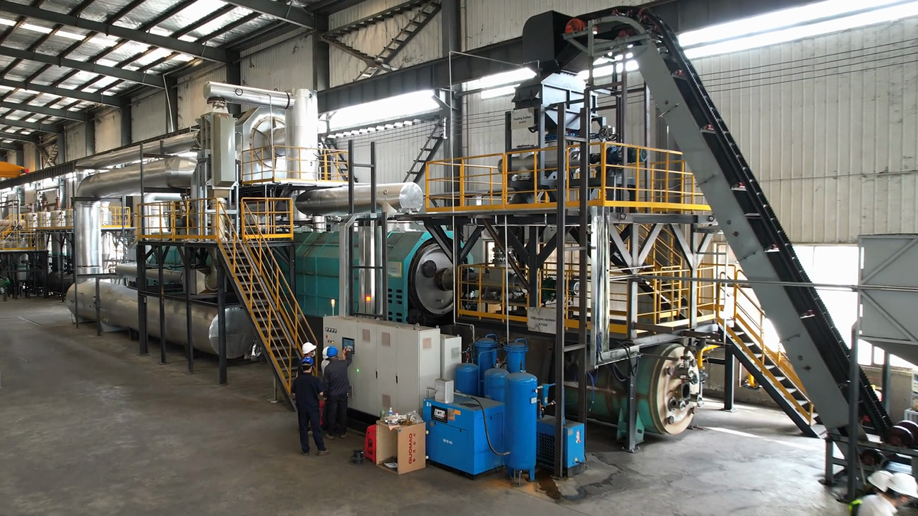
Industrial Blackgold P30 continuous pyrolysis plant site featuring continuous feeding conveyor, high-efficiency horizontal rotary reactor, PLC control cabinet, condensing system, and auto-discharging unit for high-capacity tyre, plastic, and oil sludge chemical recycling.

Closed-Loop Syngas Recycling Turns Emissions into Fuel

The non-condensable gas produced during cracking is not a waste stream; it is a fuel. After the oil fraction is condensed, the remaining syngas is scrubbed, dried and routed back to the burners that heat the reactor. This closed loop cuts external fuel demand sharply and means there is no continuous vent releasing raw gas. Surplus gas is held in a buffer tank and burned in a controlled combustion chamber rather than flared in an unmanaged way, which removes visible smoke and keeps the thermal balance steady.

Multi-Stage Flue Gas Treatment Protects Compliance

Even with syngas recycling, the furnace exhaust must be cleaned. A dependable configuration combines a cyclone or bag filter for dust, a wet scrubber with alkaline dosing for acid gases such as HCl and SO2, and an activated carbon or catalytic stage for residual volatile organics. Sulfur is the special challenge with rubber, so a tire pyrolysis plant normally adds a dedicated desulfurization tower upstream of the stack. Online analyzers for oxygen, particulates, NOx and SO2 feed the control system, so operators see exceedance risk before it becomes a violation.

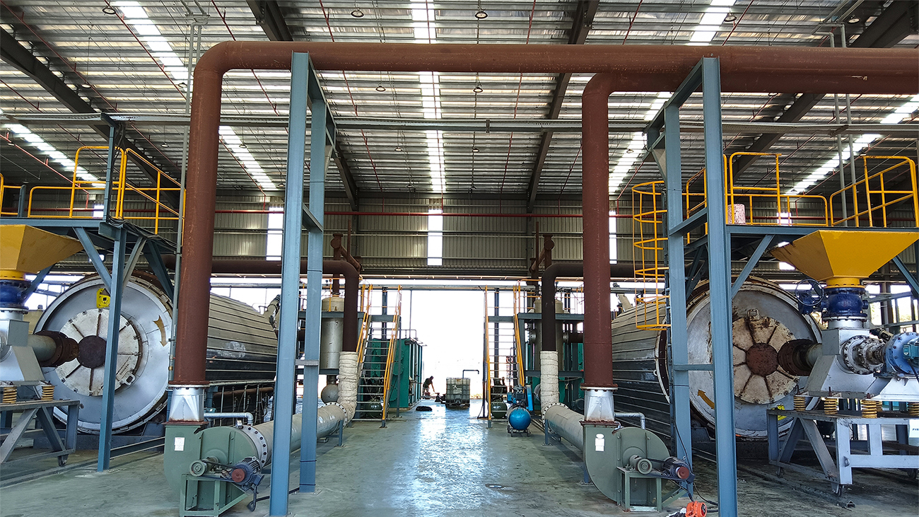
This photo captures a commercial waste tyre pyrolysis plant manufactured by Beston Group, showcasing the feeding system, pyrolysis reactor, and gas condensation system.

Negative Pressure and Sealed Discharge Control Odor

Odor is a fugitive-emission problem. It appears when sulfur-bearing vapors leak from flanges, when hot carbon black meets air, or when oil tanks breathe freely. Operators control it by keeping the whole reactor train at slight negative pressure, so any micro-leak draws air in rather than pushing vapor out. Carbon black leaves through a water-jacketed, sealed screw conveyor that cools it below ignition temperature before it contacts the atmosphere. Oil storage tanks vent through a condensing and carbon-filter line instead of an open breather.

Feedstock preparation matters as well. A plastic pyrolysis plant processing film or mixed packaging benefits from pre-sorting and drying, because moisture and chlorine-bearing polymers raise acid gas and odor loads. Calcium-based additives can capture chlorine early, protecting both the condensing system and the downstream scrubber.

Automation and Monitoring Keep Performance Consistent

Compliance is only credible when it is documented. Leading designs log reactor temperature, pressure, gas flow and stack readings in real time, alarm on drift, and interlock the feeder if a scrubber pump or fan fails. This turns emission control from a manual routine into an automatic safeguard. Investors should ask for test reports from operating references, not only design drawings. Established manufacturers such as Beston Group typically supply the full control system, spare-part support and commissioning guidance, which shortens permitting time and reduces start-up risk.

Practical Checklist for Investors and Contractors

Before committing capital, confirm five points: a sealed continuous feeder, a closed syngas loop, multi-stage flue gas cleaning, negative-pressure discharge and certified online monitoring. A pyrolysis plant that lacks any one of these may pass a short demonstration yet fail under routine inspection. Zero exceedance is not the result of a single device. It is the outcome of integrated engineering, disciplined feedstock control and transparent data, and plants built this way earn community acceptance, stable permits and predictable returns.